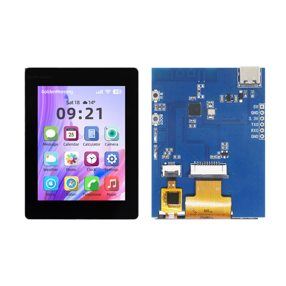
- 2.4 TFT LCD Module (IPS Panel) 320x240 product specification PDF
- label "T240B7-C10-25"
- driver: ST7789 (display), CST836U (touch)
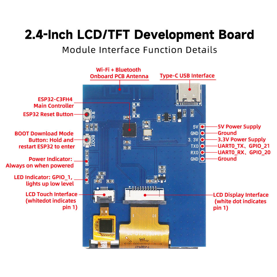
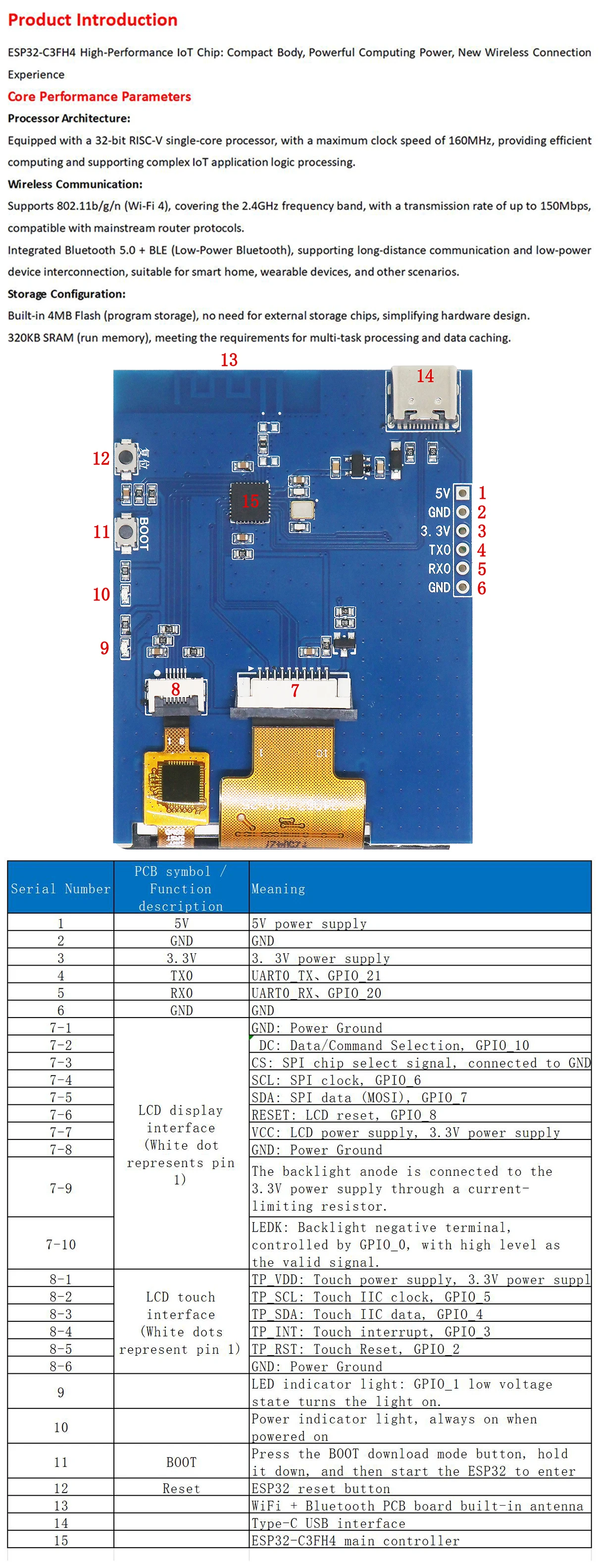
- pinout:
- UART: GPIO20 (UART0_RX), GPIO21 (UART0_TX),
- touch: GPIO2 (TP_RST), GPIO3(TP_INT), GPIO4(TP_SDA), GPIO5(TP_SCL)
- display GPIO6(SPI_CLK), GPIO7(SPI_MOSI), GPIO8(LCD_RESET), GPIO10(CD)
- LED: GPIO1 (LED)
- BOOT Button: GPIO9
- Alibaba: Shenzhen Goldenmorning Electronic Co., Ltd.
- Aliexpress: Great IT electronic components
- Aliexpress: TZT-Five-Star Store
- Aliexpress: EGBO Store
- Aliexpress: CLT IT Store
- Aliexpress: Estardyn Flagship Store
- Aliexpress: All-Electronics-Five-Stars
- Aliexpress: All-goods-are-freeshipping:
- Aliexpress: TZT teng Official Store
- Aliexpress: DIYTZT Official Store
- Aliexpress: TZT 123 Official Store
##TODO
- will it work with MicroPython LVGL? https://github.com/lvgl-micropython/lvgl_micropython
#try it with cst816u instead of cst836u
git clone https://github.com/lvgl-micropython/lvgl_micropython
cd lvgl_micropython/
python3 make.py esp32 BOARD=ESP32_GENERIC_C3 --flash-size=4 DISPLAY=st7789 INDEV=cst816u
#red LED on/off
from machine import Pin
led=Pin(1, Pin.OUT)
led.off() # ON
led.on()  # OFF

#BOOT Button @ GPIO9
from machine import Pin
p9 = Pin(9, Pin.IN)
#1=released, 0=pressed
print(p9.value())

#scan for I2C: touch controller @ 0x15
from machine import Pin, I2C
i2c = I2C(0, sda=Pin(4), scl=Pin(5)) ; i2c.scan()
  [21]
#include <Arduino_GFX_Library.h>

static const int8_t TFT_CS   = -1; // n.c.
static const int8_t TFT_DC   = 10; // DC / D/C
static const int8_t TFT_RST  = 8;  // RESET
static const int8_t TFT_MOSI = 7;  // SDA / MOSI
static const int8_t TFT_SCLK = 6;  // SCLK
static const int8_t TFT_MISO = -1; // n.c.
static const int8_t TFT_BLK  = 0;  // Backlight pin
static const int8_t LED = 1; //LED (low active)

Arduino_DataBus *bus = new Arduino_ESP32SPI(TFT_DC, TFT_CS, TFT_SCLK, TFT_MOSI, TFT_MISO);
Arduino_GFX *gfx = new Arduino_ST7789(bus, TFT_RST, 0, /*IPS*/true);

void setup() {
  // Set backlight
  pinMode(TFT_BLK, OUTPUT);
  digitalWrite(TFT_BLK, HIGH);

  pinMode(LED, OUTPUT);

  gfx->begin();
  gfx->setRotation(3);//0=portrait (top of screen @ USB-C), 1=landscape (+180 degree -> left of screen @ USB-C), 2=portrait(+180 degree -> bottom screen @ USB-C),3=landscape
  gfx->fillScreen(RGB565_WHITE);
  gfx->setCursor(10, 10);
  gfx->setTextColor(RGB565_BLACK);
  gfx->println("Hello World!");
}

void loop() {
  //blinky
  delay(1000);
  digitalWrite(LED, HIGH);
  delay(1000);
  digitalWrite(LED, LOW);
}
//Adafruit_GFX
#include <Adafruit_GFX.h>
#include <Adafruit_ST7789.h>
#include <SPI.h>

#define TFT_CS   -1 // n.c.
#define TFT_DC   10 // DC / D/C
#define TFT_RST  8  // RESET
#define TFT_MOSI 7  // SDA / MOSI
#define TFT_SCLK 6  // SCLK
#define TFT_MISO -1 // n.c.
#define TFT_BLK  0  // Backlight pin
#define LED      1  // LED (low active)

#define TFT_WIDTH 240
#define TFT_HEIGHT 320

SPIClass spi = SPIClass(/*uint8_t spi_bus = HSPI*/FSPI);
Adafruit_ST7789* tft;

void setup() {
  spi.begin(TFT_SCLK, TFT_MISO, TFT_MOSI );
  tft = new Adafruit_ST7789(/*SPIClass * spiClass*/&spi, /*int8_t cs*/TFT_CS, /*int8_t dc*/TFT_DC, /*int8_t rst*/TFT_RST);

  pinMode(TFT_BLK, OUTPUT);
  digitalWrite(TFT_BLK, HIGH);  // Set backlight

  tft->init(TFT_WIDTH, TFT_HEIGHT, /*spimode*/SPI_MODE3);
  tft->setRotation(1);  // //0=portrait (bottom of screen @ USB-C), 1=landscape (righ of screen @ USB-C), 2=portrait(top screen @ USB-C),3=landscape (left of screen @ USB-C)
  tft->fillScreen(ST77XX_BLACK);
  tft->setTextColor(ST77XX_WHITE);
  tft->setTextSize(2);
  tft->setCursor(10, 10);
  tft->print("Hello, Adafruit_GFX!");

  //red LED on
  pinMode(LED, OUTPUT);
  digitalWrite(LED, LOW);
}

void loop() {
  //blinky
  delay(500);
  digitalWrite(LED, HIGH);
  delay(500);
  digitalWrite(LED, LOW);
}